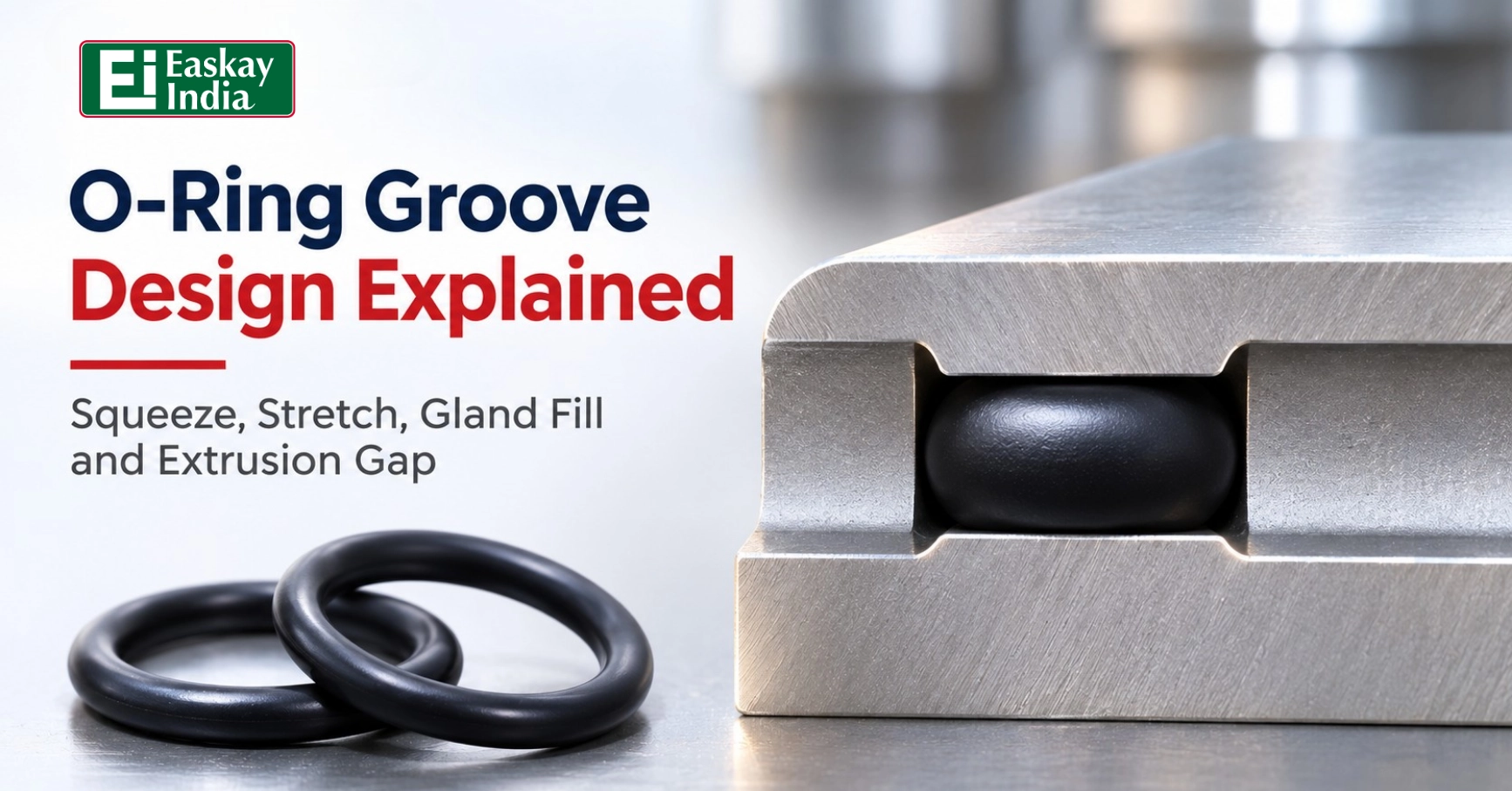
O-Ring Groove Design Explained: Squeeze, Stretch, Gland Fill and Extrusion Gap
An O-ring is one of the few sealing components that is almost completely standardised. Sizes, cross-sections, materials and hardness grades are well defined, and a good O-ring from any competent manufacturer will behave predictably. So why do O-rings still leak, extrude, twist and fail early in so many assemblies?
In a large share of cases, the answer is not the O-ring. It is the groove it sits in. The groove, also called the gland, decides how much the O-ring is squeezed, how much room it has to expand, how much it is stretched, and how large a gap it must bridge under pressure. Get those four things right and a standard O-ring in a standard material seals for years. Get one of them wrong and no change of supplier will fix it.
This guide explains O-ring groove design in plain terms for design engineers, maintenance teams and buyers who specify sealing components. It covers how an O-ring actually seals, the four numbers that define a groove, the surface finish and geometry details that matter, and the groove mistakes that cause most O-ring problems.
How an O-Ring Seals
An O-ring seals in two stages. First, when it is installed, the groove compresses its cross-section slightly. That compression, called squeeze, creates contact pressure against both sealing surfaces even with no system pressure present. Second, when system pressure arrives, it pushes the O-ring against the far wall of the groove and against the sealing surfaces, and the contact pressure rises with the system pressure. The O-ring behaves like a very viscous fluid trapped in the groove, and the more it is pressed, the harder it seals.
That second stage is why rubber works so well as a seal, and also why the groove matters so much. Rubber is effectively incompressible. It changes shape under load but not volume. If the groove does not leave room for that shape change, or leaves too much, the seal fails.
The Four Numbers That Define a Groove
1. Squeeze
O-ring squeeze is the amount the O-ring cross-section is compressed when installed, expressed as a percentage of the free cross-section. It is set by the groove depth together with the clearance between the mating parts.
Typical design practice uses different squeeze for different duties:
-
Static face seals (lids, covers, flanges): commonly around 20 to 30 percent.
-
Static radial seals (plugs, caps, fittings): commonly around 15 to 25 percent.
-
Reciprocating dynamic seals (pistons, rods): commonly around 10 to 20 percent, lower to limit friction and wear.
-
Rotary applications: very low squeeze, often only a few percent, and a dedicated rotary seal design is usually preferred.
Too little squeeze and the O-ring does not seal at low pressure, and leaks once it takes a slight compression set. Too much squeeze and friction, heat build-up and compression set rise sharply, and the O-ring may be damaged at assembly. These ranges are starting points from general industry practice; the exact figure should come from the O-ring size tables in a sealing handbook or from the manufacturer.
2. Stretch
Stretch is how much the O-ring’s inside diameter is increased when it is fitted into a groove on a shaft or piston. A small stretch holds the O-ring in the groove during assembly and is normal. Too much is harmful, because stretching an O-ring thins its cross-section, which reduces the effective squeeze, and because a highly stretched O-ring ages and cracks faster.
Common practice keeps installed stretch to around 1 to 5 percent for static grooves on shafts, and avoids anything beyond about 5 percent. For grooves in a bore, where the O-ring sits on its outside diameter, the O-ring is chosen so that its outer diameter is slightly larger than the groove, by a small percentage, so that it does not fall out.
3. Gland fill
Gland fill is the percentage of the groove’s cross-sectional area that the O-ring occupies. Because rubber cannot be compressed in volume, the groove must leave space for the O-ring to deform under squeeze, to expand with temperature, and to swell slightly in contact with the fluid.
Typical practice targets around 60 to 85 percent fill, with the lower end for applications where fluid swell or high temperature is expected. A gland fill approaching 100 percent is a failure waiting to happen. When the O-ring has nowhere to go, it generates very high stresses, extrudes into any clearance it can find, and can crack or split the housing in extreme cases.
4. Extrusion gap
The O-ring extrusion gap is the clearance between the two mating parts on the low-pressure side of the groove. Under pressure, the O-ring is pushed towards that gap, and if the gap is too large for the pressure and the O-ring hardness, the rubber flows into it and is nibbled away. The result is the characteristic ragged, chewed edge of an extruded O-ring.
The permissible gap falls as pressure rises and rises with O-ring hardness. A 70 Shore A O-ring is the usual general purpose choice. For higher pressures, designers either reduce the gap, move to a harder compound such as 90 Shore A, or add backup rings behind the O-ring. Many handbooks suggest considering backup rings with a standard 70 Shore A O-ring once pressures reach the region of 100 bar, and earlier if the gap cannot be controlled. Where hardness is being chosen, our guide to rubber hardness, elasticity and durability explains what the Shore A number means in practice.
A Simple Worked Example
Consider a static radial seal using an O-ring with a 3.53 mm cross-section, a common standard size.
-
Target squeeze: 20 percent. Groove depth is then roughly 3.53 x 0.80 = 2.82 mm (ignoring the diametral clearance for simplicity).
-
O-ring cross-sectional area: approximately 9.8 square mm.
-
Target gland fill: 75 percent. Required groove area is 9.8 / 0.75 = about 13.1 square mm.
-
Groove width is then 13.1 / 2.82 = about 4.6 mm.
Those figures sit close to the standard groove dimensions published for this cross-section, which is reassuring, but the point of the example is the logic: depth sets squeeze, width sets fill, and both must be chosen together. The example is illustrative; always confirm against published size tables for the specific application.
Geometry Details That Decide Success
Beyond the four numbers, several small details make the difference between an O-ring that lasts and one that does not.
Groove shape. A plain rectangular groove is standard and suits most applications. Dovetail and half-dovetail grooves are used on face seals where the O-ring must stay in place when the cover is removed, such as lids on vessels and vacuum chambers. They are more expensive to machine and need careful fill calculation.
Corner radii. The bottom corners of the groove should have a small radius rather than a sharp internal corner, which concentrates stress in the rubber. The top edges, where the O-ring passes during assembly, should be broken with a small radius so they do not cut it.
Lead-in chamfers. Wherever an O-ring has to pass over an edge during assembly, such as a piston entering a bore or a plug entering a port, a chamfer of around 15 to 20 degrees guides the O-ring in without nicking it. A missing chamfer is one of the most common causes of O-rings that leak from day one.
Cross holes, ports and threads. An O-ring that must slide across a drilled port, a keyway or a thread during assembly or operation will be cut. Where this cannot be designed out, the edges must be heavily radiused or the O-ring protected during assembly.
Face seal orientation. On a face seal, the O-ring moves towards the low-pressure side under load. If pressure comes from inside, the O-ring should seat against the outer wall of the groove, so the groove outer diameter is matched to the O-ring outer diameter. If pressure comes from outside, the groove inner diameter is matched to the O-ring inner diameter. Getting this backwards leaves the O-ring unsupported.
Surface Finish
The groove and the mating surfaces must be smooth enough for the rubber to seal against, but not so polished that a dynamic seal cannot retain a lubricating film. Typical design guidance is:
-
Dynamic sealing surfaces (the rod or bore the O-ring slides on): around Ra 0.4 micrometres or finer.
-
Static sealing surfaces: around Ra 0.8 micrometres.
-
Groove side walls and bottom: up to about Ra 1.6 micrometres.
Surface finish should be free of scratches, tool marks running across the seal line, and machining lead. On dynamic surfaces, lead acts like a screw thread that pumps fluid past the seal.
Temperature, Fluid and Pressure Change the Numbers
A groove designed at room temperature with a dry O-ring sees very different conditions in service:
-
Heat expands the rubber, increasing fill and squeeze. High-temperature applications need lower initial fill.
-
Fluid swell increases volume in the same way. If the fluid is known to swell the compound by several percent, allow for it in the fill calculation, or choose a more resistant compound.
-
Cold shrinks and stiffens the rubber, reducing squeeze. Low-temperature applications need enough squeeze to remain sealed when the O-ring contracts.
-
Pressure cycling works the O-ring back and forth across the groove and accelerates extrusion if the gap is marginal.
When the operating conditions are far from ambient, the standard tables are a starting point, not the final answer.
Nine Groove Design Mistakes That Cause O-Ring Failure
-
Groove too deep. Squeeze is too low; the seal leaks at low pressure and after slight compression set.
-
Groove too shallow. Squeeze is too high; friction, heat and compression set rise, and the O-ring may be cut on assembly.
-
Groove too narrow. Fill is too high; the O-ring has nowhere to expand and extrudes or splits the housing.
-
Groove too wide. The O-ring rolls and twists in a dynamic application, producing a spiral failure.
-
Excessive stretch. Thinned cross-section, reduced squeeze and early cracking.
-
Sharp corners and no chamfer. O-rings nicked at assembly leak from day one.
-
Extrusion gap too large for the pressure. Ragged, nibbled O-rings and a seal that fails under load.
-
Wrong face seal orientation. The O-ring sits against the wrong wall and is unsupported under pressure.
-
Poor surface finish or machining lead. Leakage along tool marks and pumping of fluid past dynamic seals.
Most of these can be read from the failed O-ring itself. Flattened means over-squeeze or heat; nibbled means extrusion; a spiral cut means rolling in a wide groove; a clean cut means assembly damage.
O-Rings and Sealing Rings from Easkay India
Easkay India manufactures moulded industrial O-rings, see our O-rings in standard and non-standard sizes, in NBR, EPDM, silicone, FKM and other specified compounds, with the hardness and dimensions your groove design calls for. The range also includes PU O-rings for applications that need high wear and extrusion resistance, silicone rubber sealing rings and moulded rubber rings for custom sections. Parts are made to drawing, sample or dimensional specification, and approved specifications are retained for repeat supply.
As an ISO 9001:2015 certified O-ring manufacturer in India since 1977, we can review your groove dimensions, pressure, temperature and fluid before you commit to a size and compound. Share your groove drawing and operating conditions and we will confirm the O-ring size, hardness and material that suit it.
Frequently Asked Questions
1. What is O-ring squeeze and how much is normal?
Squeeze is the percentage by which the O-ring cross-section is compressed when installed. Common practice uses roughly 20 to 30 percent for static face seals, 15 to 25 percent for static radial seals, and 10 to 20 percent for reciprocating dynamic seals, with the exact figure taken from published size tables.
2. What is gland fill and why must it be below 100 percent?
Gland fill is the share of the groove area the O-ring occupies. Rubber cannot be compressed in volume, so the groove must leave room for the O-ring to deform, expand with heat and swell in the fluid. Typical fill is around 60 to 85 percent.
3. Why does my O-ring have a ragged, nibbled edge?
That is extrusion. The clearance gap on the low-pressure side is too large for the pressure and the O-ring hardness. Reduce the gap, use a harder compound, or add a backup ring.
4. Do I need a chamfer where the O-ring is fitted?
Yes, wherever the O-ring passes over an edge during assembly. A lead-in chamfer of around 15 to 20 degrees, with the edge radiused, prevents the O-ring being nicked, which is a common cause of leaks on a new assembly.
5. Can Easkay India make O-rings for a non-standard groove?
Yes. Easkay India manufactures O-rings and sealing rings in standard and non-standard sizes, to drawing or sample, in the compound and hardness your application needs.
Conclusion
The O-ring is the simplest part of a seal. The groove is where the engineering happens. Set the squeeze for the duty, keep the fill well below full, limit the stretch, control the extrusion gap for the pressure, add the chamfers and radii, and specify the surface finish. Do those things and a standard O-ring in a standard compound will do its job quietly for years. If a seal keeps failing, look at the groove before you look for a new O-ring supplier, and if you would like a second opinion on a groove design, share it with our team.
Recent Posts